- Part 1: Using a queue
- Part 2: Sorting
- Part 3: The observer pattern
- Part 4: Go channels
This post is the third in a series, exploring a random assortment of techniques, data-structures etc. Each of which can be used to solve a puzzle from the 2015 edition of Advent Of Code, namely the first part of Day 7: Some Assembly Required.
See Part 1 for details on Advent of Code in general, as well as a summary introduction to the puzzle itself.
In this post we’ll take a look at how the observer pattern can be used to solve the dependencies between instructions.
Observer
This pattern is used in object oriented programming and it can solve a one-to-many dependency between objects without making them tightly coupled.
The term was originally coined in the “Gang of Four” book where the intent of the pattern states:
“Define a one-to-many dependency between objects so that when one object changes state, all its dependents are notified and updated automatically.”
Excerpt From: Gamma, Erich. “Design Patterns: Elements of Reusable Object-Oriented Software”. Apple Books.
If we take a look at the class and sequence diagrams from the Wikipedia article it makes a bit more sense how something like this could be implemented in an object oriented fashion.
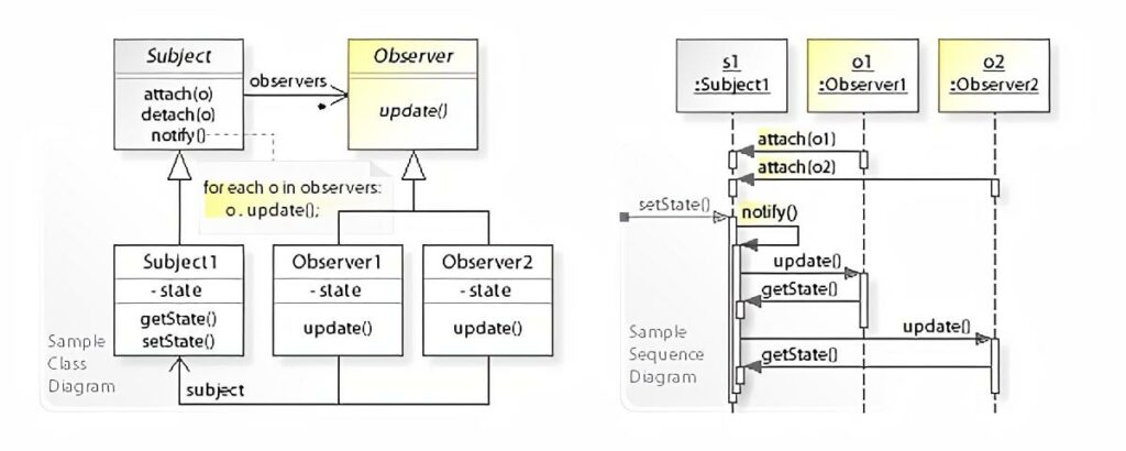
The Subject keeps an internal collection of all of its observers and when its state changes, it notifies each of them by calling their update method. Each Observer can then in turn get whatever state they might depend on by calling a getter on the Subject. In this example Subject has a getState method.
The beauty of this is that the Subject can be agnostic about its observers, as long as they provide an update method.
Instructions and objects
The question is then, how do we model our puzzle in an object oriented manner, so we can apply this pattern?
In part 2 we looked into how we could define dependencies between wires on the left- and righthand sides in the instructions. In the simplest application of this idea, we could define two objects, A and B where A would represent the lefthand, or the expression if you will and B would represent the wire output on the right.
B would observe A, and B itself would possibly be observed by a separate instance of A and so on and so forth until all connections are joined up.
Even though both of these objects exhibit identical behaviour, according to the original definition of Subject and Observer, they must behave differently in the way they each handle their state.
An instance of A would need complex logic in order to act as all the different forms of expressions encountered.
Signals, wires and gates
Perhaps it would be better to avoid the complex logic and go the way of Smalltalk by making everything an object.
Let’s imagine that we split instructions down into their basest components, namely the Signal, the Wire and the Gate. That would allow us to define the same observability relationships amongst the individual components of an expression as we could between an expression and an output from the model above.
If we use the sample input as a basis:
123 -> x
456 -> y
x AND y -> d
x OR y -> e
x LSHIFT 2 -> f
y RSHIFT 2 -> g
NOT x -> h
NOT y -> i
And then draw the relationships in this split-up manner, we get the following graph:

For resemblance to the original instructions the arrows are pointing opposite of the worded meaning of observe. I.e. y has an incoming arrow from 456, meaning y observes 456.
Solution
Despite alluding to Smalltalk above, and the fact that all objects in Smalltalk provides this pattern out of-the-box, I’ve chosen another language which I have about the same amount of real-world experience with. That is to say, little to none.
That language is Java and the reason is, both because it has a built-in implementation in the form of:
But also because Java was the first place I came across this pattern, all the way back when I was a student.
Note: Apparently both of these were deprecated already back in 2016, but in the context of this solution, I don’t think we need to worry about the stated pitfalls.
It is very verbose, but hey that’s Java for you. Here’s the source:
There might be a better way, but here’s how it can be run from the commandline:
$ javac 7p1-observer.java && java SomeAssemblyRequired < 7.inNote: There’s no bounding of 16 bit values in this solution. It’s not because int in Java is 16 bits. In fact it’s a 32-bit signed two’s complement integer. The reason is rather that I noticed the output was correct despite just using int. Perhaps it wasn’t even needed to begin with, or perhaps I was just lucky to have an input that never generated any integer overflows.
In any case, let’s take a look at the code. Starting out there’s the SignalProvider interface, which defines access to the main piece of state for all of our objects. Each of the base classes SignalInput, Wire and Gate implement this interface, in order to provide a uniform way for an observer to get the value of a signal update.
Next up is the SignalInput class, which is quite simple, because it doesn’t need to implement Observer. A signal doesn’t depend on any inputs.
There isn’t all that much to the Wire class either. It has an id aside from its signal and needs to be able to both be observed as well as observe others. When its update method triggers, it will get the value of the signal from the observed signal provider store it and then notify its own observers as well.
Unsurprisingly the Gate and its derived classes are where the logic of the program lives. Gate is an abstract class, because we need to differentiate the different logical operations a gate can perform. Like Wire it must extend Observable and implement Observer, because it has both input and output.
The only thing to really note about the concrete gate classes is how they differ depending on whether there’s a single or multiple inputs.
Take the AndGate for instance. Since it cannot produce an output before it has a signal on both incoming wires, (or inputs), it has to store the first incoming signal value and only on receiving the second, can it update its own signal value and notify its observers.
The unary gates for NOT, RSHIFT and LSHIFT doesn’t need to do this because, they have everything they need from the get-go.
The next section defines all the different Instruction classes. Each Instruction class has the ability to perform a modification on an instance of Circuit. The modification corresponds to the input instruction the class represents. This really boils down to connecting inputs and outputs via addObserver, and possibly putting gates in between.
There’s one of the Instruction classes, SignalImmediateInstruction, that sticks out from the rest because it has the addition of a trigger method. The reason for having this, is as a means to defer the running of the circuit until it’s been fully assembled.
You can imagine setting signal values immediately after an instruction has been performed on a circuit having little effect, simply because all observers might not have been attached at the time the instruction is encountered in the input. Having trigger allows to postpone this until all instructions have been carried out.
The InstructionFactory is really just a place to put the heavy handed input handling which matches input instructions by regular expressions. Not quite the nimble read of Ruby unfortunately.
The Circuit class is a wrapper around the associate array we’ve been using previously, with the added convenience that it dynamically generates new Wire instances, if one is requested via getWire that wasn’t already present. This is makes the logic of Instruction classes easier, as they don’t need to manage creation of wires. They just retrieve and connect them.
Finally our main entrypoint is the SomeAssemblyRequired class. It mimics the input handling from the previous solutions by reading lines from stdin, passing them on to the InstructionFactory and performing the returned instructions on a Circuit instance.
Once all instructions are done, it goes through each SignalImmediateInstruction and runs the aforementioned trigger method. This starts the chain-reaction of observables notifying observers of changes and so on and so forth.
After this all wires should have their correct signal values, so we just fetch the one for “a” and print out the result.
Run-time analysis
If we think about all the connections between the objects that represent the circuit as a graph, in the same manner as we did previously for the sample input, we can then reason that the circuit must be a directed acyclic graph, or DAG.
It’s directed because each object has one or more inputs and one output, dictating a direction for the signal to travel. It must be acyclic as well, since if it wasn’t, a signal in the circuit would just wind up travelling around in a wire loop forever and we couldn’t construct a program that simulates it.
We know that each connection in such a graph would represent a callback from an Observer to and Observable, so if we can figure out how many connections there is in the graph, we can derive the run-time complexity based on that.
If we have a DAG of n nodes, then pick any node from the graph, let’s call it n0. The maximum number of nodes it can be connected to, without creating a cycle, is n - 1. That is, all but itself.
Let’s assume n0 has that many connections. Then let’s pick another node, n1, this node can have a maximum of n - 2 connections, since it cannot connect to itself nor n0.
Thus the maximum number of connections in a circuit is the the familiar arithmetic progression: n + (n - 1) + (n - 2) + .... + 2 + 1 = n * (n + 1) / 2.
It would appear we still haven’t escaped that O(n^2) complexity.
Now it goes to reason, that our particular circuit isn’t as strongly connected as that and the amount of connections is much closer to some constant times n, which would probably yield a run-time closer to linear, but for the worst case, this is probably what should be expected.
Memory Usage
These numbers are based on (Runtime.totalMemory - Runtime.freeMemory) / 1024L for a KiB measure. Again, I’m not really all that familiar with Java, so if there’s a more accurate way to do it, feel free to leave a comment.
I ran the garbage collector before and after the main application logic and then stored the memory values as indicated above:
$ javac 7p1-observer.java && java SomeAssemblyRequired < 7.in
Signal ultimately provided to wire a: 16076
Memory before initial GC: 2621KiB
Memory after initial GC / before run: 276KiB (diff: -2344KiB)
Memory after run: 8141KiB (diff: 7864KiB)
Memory after final GC: 581KiB (diff: -7559KiB)
I have no idea why so much memory is allocated before the program runs, but the increase of ~7.8MiB is probably valid. I would expect this to be fairly memory hungry after all, due to the very large number of objects being created, each invoking callbacks for each signal propagation.
In the next post we’ll take a look at a solution using Go channels to simulate the wire connections in a concurrent way.