Spelunking Advent of Code, Some Assembly Required – part 3 of 4 – The Observer Pattern

This post is the third in a series, exploring a random assortment of techniques, data-structures etc. Each of which can be used to solve a puzzle from the 2015 edition of Advent Of Code, namely the first part of Day 7: Some Assembly Required.

See Part 1 for details on Advent of Code in general, as well as a summary introduction to the puzzle itself.

In this post we’ll take a look at how the observer pattern can be used to solve the dependencies between instructions.

Observer

This pattern is used in object oriented programming and it can solve a one-to-many dependency between objects without making them tightly coupled.

The term was originally coined in the “Gang of Four” book where the intent of the pattern states:

“Define a one-to-many dependency between objects so that when one object changes state, all its dependents are notified and updated automatically.”

Excerpt From: Gamma, Erich. “Design Patterns: Elements of Reusable Object-Oriented Software”. Apple Books.

If we take a look at the class and sequence diagrams from the Wikipedia article it makes a bit more sense how something like this could be implemented in an object oriented fashion.
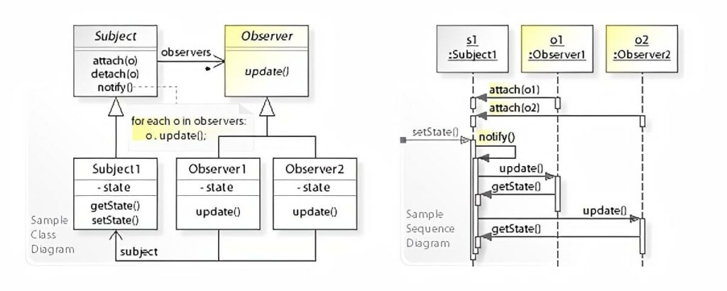
Illustration of the observer pattern as a UML class and sequence diagram.
By Vanderjoe – Own work, CC BY-SA 4.0, https://commons.wikimedia.org/w/index.php?curid=61809260

The Subject keeps an internal collection of all of its observers and when its state changes, it notifies each of them by calling their update method. Each Observer can then in turn get whatever state they might depend on by calling a getter on the Subject. In this example Subject has a getState method.

The beauty of this is that the Subject can be agnostic about its observers, as long as they provide an update method.

Instructions and objects

The question is then, how do we model our puzzle in an object oriented manner, so we can apply this pattern?

In part 2 we looked into how we could define dependencies between wires on the left- and righthand sides in the instructions. In the simplest application of this idea, we could define two objects, A and B where A would represent the lefthand, or the expression if you will and B would represent the wire output on the right.

B would observe A, and B itself would possibly be observed by a separate instance of A and so on and so forth until all connections are joined up.

Even though both of these objects exhibit identical behaviour, according to the original definition of Subject and Observer, they must behave differently in the way they each handle their state.

An instance of A would need complex logic in order to act as all the different forms of expressions encountered.

Signals, wires and gates

Perhaps it would be better to avoid the complex logic and go the way of Smalltalk by making everything an object.

Let’s imagine that we split instructions down into their basest components, namely the Signal, the Wire and the Gate. That would allow us to define the same observability relationships amongst the individual components of an expression as we could between an expression and an output from the model above.

If we use the sample input as a basis:

123 -> x
456 -> y
x AND y -> d
x OR y -> e
x LSHIFT 2 -> f
y RSHIFT 2 -> g
NOT x -> h
NOT y -> i

And then draw the relationships in this split-up manner, we get the following graph:

Using the sample input as an example, illustration of observability where everything is split out into own objects.
Sample instructions as an observer graph

For resemblance to the original instructions the arrows are pointing opposite of the worded meaning of observe. I.e. y has an incoming arrow from 456, meaning y observes 456.

Solution

Despite alluding to Smalltalk above, and the fact that all objects in Smalltalk provides this pattern out of-the-box, I’ve chosen another language which I have about the same amount of real-world experience with. That is to say, little to none.

That language is Java and the reason is, both because it has a built-in implementation in the form of:

But also because Java was the first place I came across this pattern, all the way back when I was a student.

Note: Apparently both of these were deprecated already back in 2016, but in the context of this solution, I don’t think we need to worry about the stated pitfalls.

It is very verbose, but hey that’s Java for you. Here’s the source:

There might be a better way, but here’s how it can be run from the commandline:

$ javac 7p1-observer.java && java SomeAssemblyRequired < 7.in

Link to my input.

Note: There’s no bounding of 16 bit values in this solution. It’s not because int in Java is 16 bits. In fact it’s a 32-bit signed two’s complement integer. The reason is rather that I noticed the output was correct despite just using int. Perhaps it wasn’t even needed to begin with, or perhaps I was just lucky to have an input that never generated any integer overflows.

In any case, let’s take a look at the code. Starting out there’s the SignalProvider interface, which defines access to the main piece of state for all of our objects. Each of the base classes SignalInput, Wire and Gate implement this interface, in order to provide a uniform way for an observer to get the value of a signal update.

Next up is the SignalInput class, which is quite simple, because it doesn’t need to implement Observer. A signal doesn’t depend on any inputs.

There isn’t all that much to the Wire class either. It has an id aside from its signal and needs to be able to both be observed as well as observe others. When its update method triggers, it will get the value of the signal from the observed signal provider store it and then notify its own observers as well.

Unsurprisingly the Gate and its derived classes are where the logic of the program lives. Gate is an abstract class, because we need to differentiate the different logical operations a gate can perform. Like Wire it must extend Observable and implement Observer, because it has both input and output.

The only thing to really note about the concrete gate classes is how they differ depending on whether there’s a single or multiple inputs.

Take the AndGate for instance. Since it cannot produce an output before it has a signal on both incoming wires, (or inputs), it has to store the first incoming signal value and only on receiving the second, can it update its own signal value and notify its observers.

The unary gates for NOT, RSHIFT and LSHIFT doesn’t need to do this because, they have everything they need from the get-go.

The next section defines all the different Instruction classes. Each Instruction class has the ability to perform a modification on an instance of Circuit. The modification corresponds to the input instruction the class represents. This really boils down to connecting inputs and outputs via addObserver, and possibly putting gates in between.

There’s one of the Instruction classes, SignalImmediateInstruction, that sticks out from the rest because it has the addition of a trigger method. The reason for having this, is as a means to defer the running of the circuit until it’s been fully assembled.

You can imagine setting signal values immediately after an instruction has been performed on a circuit having little effect, simply because all observers might not have been attached at the time the instruction is encountered in the input. Having trigger allows to postpone this until all instructions have been carried out.

The InstructionFactory is really just a place to put the heavy handed input handling which matches input instructions by regular expressions. Not quite the nimble read of Ruby unfortunately.

The Circuit class is a wrapper around the associate array we’ve been using previously, with the added convenience that it dynamically generates new Wire instances, if one is requested via getWire that wasn’t already present. This is makes the logic of Instruction classes easier, as they don’t need to manage creation of wires. They just retrieve and connect them.

Finally our main entrypoint is the SomeAssemblyRequired class. It mimics the input handling from the previous solutions by reading lines from stdin, passing them on to the InstructionFactory and performing the returned instructions on a Circuit instance.

Once all instructions are done, it goes through each SignalImmediateInstruction and runs the aforementioned trigger method. This starts the chain-reaction of observables notifying observers of changes and so on and so forth.

After this all wires should have their correct signal values, so we just fetch the one for “a” and print out the result.

Run-time analysis

If we think about all the connections between the objects that represent the circuit as a graph, in the same manner as we did previously for the sample input, we can then reason that the circuit must be a directed acyclic graph, or DAG.

It’s directed because each object has one or more inputs and one output, dictating a direction for the signal to travel. It must be acyclic as well, since if it wasn’t, a signal in the circuit would just wind up travelling around in a wire loop forever and we couldn’t construct a program that simulates it.

We know that each connection in such a graph would represent a callback from an Observer to and Observable, so if we can figure out how many connections there is in the graph, we can derive the run-time complexity based on that.

If we have a DAG of n nodes, then pick any node from the graph, let’s call it n0. The maximum number of nodes it can be connected to, without creating a cycle, is n - 1. That is, all but itself.

Let’s assume n0 has that many connections. Then let’s pick another node, n1, this node can have a maximum of n - 2 connections, since it cannot connect to itself nor n0.

Thus the maximum number of connections in a circuit is the the familiar arithmetic progression: n + (n - 1) + (n - 2) + .... + 2 + 1 = n * (n + 1) / 2.

It would appear we still haven’t escaped that O(n^2) complexity.

Now it goes to reason, that our particular circuit isn’t as strongly connected as that and the amount of connections is much closer to some constant times n, which would probably yield a run-time closer to linear, but for the worst case, this is probably what should be expected.

Memory Usage

These numbers are based on (Runtime.totalMemory - Runtime.freeMemory) / 1024L for a KiB measure. Again, I’m not really all that familiar with Java, so if there’s a more accurate way to do it, feel free to leave a comment.

I ran the garbage collector before and after the main application logic and then stored the memory values as indicated above:

$ javac 7p1-observer.java && java SomeAssemblyRequired < 7.in
Signal ultimately provided to wire a: 16076
Memory before initial GC: 2621KiB
Memory after initial GC / before run: 276KiB (diff: -2344KiB)
Memory after run: 8141KiB (diff: 7864KiB)
Memory after final GC: 581KiB (diff: -7559KiB)

I have no idea why so much memory is allocated before the program runs, but the increase of ~7.8MiB is probably valid. I would expect this to be fairly memory hungry after all, due to the very large number of objects being created, each invoking callbacks for each signal propagation.


In the next post we’ll take a look at a solution using Go channels to simulate the wire connections in a concurrent way.
Spelunking Advent of Code, Some Assembly Required – part 2 of 4 – Sorting

This post is the second in a series, exploring a random assortment of techniques, data-structures etc. Each of which can be used to solve a puzzle from the 2015 edition of Advent Of Code, namely the first part of Day 7: Some Assembly Required.

See Part 1 for details on Advent of Code in general, as well as a summary introduction to the puzzle itself.

In this post we’ll take a look at how we can use sorting to solve the issue of instructions having arbitrary ordering in the input. We’ll be using Ruby again so we can do some run-time comparisons with the Queue based solution from Part 1.

Sorting

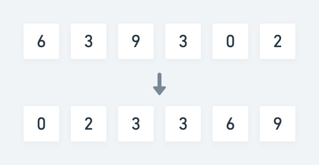
In computer science sorting usually means ordering elements of a list or an array in a lexicographical or numerical manner. E.g. for a random list of numbers, a sorted version could look like so:

Unsorted to sorted

Each element compared to the next follows the relation a ≤ b. For numbers this relation is trivial because it has a strict mathematical definition. For words and letters it’s much the same, as each can be boiled down to a numeric representation as well.

In our case however each instruction isn’t necessarily directly comparable. Let’s take two random instructions from my input as an example:

fs AND fu -> fv
bz AND cb -> cc

If we just look at these two instructions, there isn’t any meaningful way that we can say that one should be ordered before the other. The relation between the two is simply lacking context.

Looking at each instruction individually however, we can reason about the relation between individual wires instead.

If we formulate the relation as depends on, for the above two instructions, we can say that fv depends on fs and fu, and that cc depends on bz and cb.

This should be enough to create an ordering definition that makes it possible to sort all instructions in a way where they can be carried out from top to bottom.

An instruction A with a lefthand side reference to a wire X depends on an instruction B with a righthand reference to a wire X.

As an example, the instruction ff AND fh -> fi depends on the instruction et OR fe -> ff. This means we must place the former after the latter in the the list of instructions.

Solution

The idea of this solution is that by re-ordering the instructions according to the above definition beforehand, we can then carry them out one by one, as is, and any wire will always have a signal by the time we reach an instruction that references it.

As in Part 1, we keep track of the overall state of the circuit in an associative array, which maps the name of a wire to its current signal value. Additionally in this version, we keep a list of wires which have resolved dependencies, which will form the decision basis for the ordering of sorted instructions.

The solution has three separate parts. Seeding, extraction and execution. Here’s the pseudo algorithm:

Outline

  1. Find the instructions that has no dependencies and use them to seed the sorted collection.
  2. While there’s still instructions left:
    1. Find the ones with resolved dependencies, extract and append them to the sorted collection.
  3. Execute the sorted instructions from top to bottom and store wire signals along the way.
  4. Print out the value of desired target wire.

Here’s the Ruby source:

Note: We have to do the same kind of bounding as in Part 1, in order to maintain 16-bit values throughout .

On lines 17-21 we do the initial seeding. Ruby has a .partition method which divides an enumerable into two new arrays based on the value of a predicate for each element.

We use this to separate all the instructions which we know have no dependencies, from the ones that have. Namely the instructions that directly assigns a signal to a wire. For each matching instruction we append the name of the output wire to the list of resolved wires, so we can use it for lookup later.

Lines 23-54 is really the meat of the program, and consists of an outer loop and an inner loop in the form of another .partition. The idea is pretty much the same as with the initial seeding, except this time we keep going until we’ve moved all remaining instructions into the sorted collection.

On each iteration of the outer loop, we pluck some subset of instructions which all have resolved wire dependencies and move them to sorted ones. At the same time we mark the output wires of those instructions as resolved as well.

Finally on lines 56-75 we carry out each sorted instruction and update the wire signals on the circuit as we go.

Input is again read from stdin, so the program can be run like so:

$ ruby 7p1-sort.rb < 7.in

Run-time analysis

As with the Queue solution, I’m going to disregard regex matches and hash lookups, since they mostly likely are not the dominating factor.

Let’s look at each separate part of the program. Seeding and execution each runs through the list of instructions once yielding a O(n) + O(n) = O(n) run-time.

The most work is obviously done in the extraction part where we have a nested loop.

The outer loop is not bounded strictly by n, since we’ve already extracted some amount m of seed instructions. At the same time we extract some amount o of instructions each iteration, so the outer loop will never run n - m iterations because o > 0. Inversely the inner loop will pluck more and more instructions, due to more resolved wires. This makes o grow monotonically with each iteration of the outer loop.

However, since we cannot know for certain exactly how many instructions are extracted on each pass, we have to fall back on knowing that at least one instruction will be. This is yields the same familiar progression as in Part 1:

n + (n - 1) + … + 2 + 1

Good old O(n^2). That means we can throw out the lesser O(n) run-times of the seeding and the execution part.

We’re not quite done yet though. Inside that inner loop hides another lookup. Every time we test if a wire has been resolved, we do so by using .include. Which is most likely an O(n) linear search operation.

That means the final run-time complexity is O(n^3).

I’m sure there’s some tricks to make this approach more viable, but I’ll leave that up to the astute reader.

Still the output is small enough that the programs runs fast:

$ time ruby 7p1-sort.rb < 7.in
Signal ultimately provided to wire a: 16076

real    0m0.329s
user    0m0.260s
sys     0m0.051s

If we consider the running time of the Queue based approach, 0m0.225s, this is almost 50% slower by comparison however.

Memory usage

We’ll re-use the profiling approach from Part 1 and from that we can see the following allocations:

$ ruby 7p1-sort.rb < 7.in | head -3
Signal ultimately provided to wire a: 16076
Total allocated: 15.38 MB (248603 objects)
Total retained:  60.86 kB (1022 objects)

Again the sorting based approach takes a hit. It allocates about 4.3x the number of objects and uses about 3.3x the amount of memory compared to using a Queue.

Looking at which classes take up the most amount of memory this time around we get:

allocated memory by class
-----------------------------------
   7.10 MB  String
   5.89 MB  MatchData
   2.38 MB  Array
  14.43 kB  Hash
   72.00 B  Thread::Mutex

It’s not entirely surprising to see MatchData high up the list again, since we’re now doing the Regexp#=== pattern for the case statements in two different places.

I was a bit surprised at exactly how much String data was being allocated, so taking a look at another section of the MemoryProfiler output reveals that the most memory is allocated at the following lines:

allocated memory by location
-----------------------------------
   5.58 MB  7p1-sort.rb:31 (:27)
   2.07 MB  7p1-sort.rb:37 (:33)
   1.76 MB  7p1-sort.rb:41 (:37)
   1.31 MB  7p1-sort.rb:45 (:41)
   1.03 MB  7p1-sort.rb:47 (:43)

The line numbers are slightly off, compared to the version in the above gist, because that one doesn’t include the lines for MemoryProfiler. The ones in parenthesis correspond to the gist version.

The top offender is where we split an instruction into an expression and an output part on line 27. The other four are all MatchData from the regex matches in the following case block. It does make sense though, since these are all part of the inner loop.

All in all this approach is definitely a step back performance wise, compared to the Queue based solution.


In the next post we’ll take a look at a solution based on the observer pattern, which entirely sidesteps the issue of arbitrary instruction ordering, by managing dependencies as observers. Part 3.

Spelunking Advent of Code, Some Assembly Required – part 1 of 4 – Using a queue

This post is the first in a series, exploring a random assortment of techniques, data-structures etc. Each of which can be used to solve a puzzle from the 2015 edition of Advent Of Code, namely the first part of Day 7: Some Assembly Required.

In case you’re not familiar with Advent of Code, it is an Advent calendar for programmers of all levels and consists of a series of daily Christmas themed programming challenges. It’s made by Eric Wastl and runs from December 1st until the 24th and usually has an overarching theme and narrative from start to finish.

The puzzles tends to start off on the easier side and then gets progressively harder as the month goes along.

Spoiler alert: I’ve never actually managed to complete all 24 puzzles in time for Christmas in any year. Some of the puzzles are simply too hard for me and in fact, at the time of writing, I’ve only managed to complete an entire calendar a single year – 2017. Now whilst there is a competition aspect to Advent of Code, this seems mostly dominated by people who do competitive programming. For other mere mortals, many use it as an opportunity to get acquainted with a new language for instance. I feel the learning aspect is really the core of Advent of Code rather than the competition.

It’s about the journey, not the destination.

Obviously solutions can be looked up if you get stuck. This post itself is a case in point. Personally though, I prefer to fail a puzzle if I cannot figure it out. Sometimes it takes tumbling a problem around in your head for awhile before you can find a new approach or another place to look for inspiration. By looking up solutions, you might rob yourself of a very rewarding Aha! moment.

The puzzle

The story behind this one, is that we need to help little Bobby Tables assemble an electronics circuit brought to him by Santa.

We are given a series of instructions, each describing a step in how to assemble the circuit using wires and bitwise logic gates. Once assembled, we should be able to answer what signal value a specific wire has if the circuit was live.

Here is the sample circuit provided as an example, along with the expected output on each wire after the circuit has been run:

123 -> x
456 -> y
x AND y -> d
x OR y -> e
x LSHIFT 2 -> f
y RSHIFT 2 -> g
NOT x -> h
NOT y -> i
d: 72
e: 507
f: 492
g: 114
h: 65412
i: 65079
x: 123
y: 456

Input

There’s a few things to note which isn’t apparent from the above sample. The following points are revealed by looking at the real puzzle input instead:

  1. Ordering of instructions is arbitrary. That means instructions can reference wires, before they’ve been assigned a signal.
  2. Direct signal assignment can come from both numbers and wires.
  3. The lefthand side of an AND instruction can be both a number and a wire.
  4. Wire identifiers are a maximum of two letters.

My version of the full input is available here.

Due to the arbitrary ordering, instructions cannot necessarily be carried out in a top-to-bottom manner. There might be a dependency issue on the propagation of signal values, which has to be resolved beforehand. E.g., and in other words, we cannot carry out an instruction with two wires if they don’t both have a signal.

Why this particular puzzle?

Many puzzles has some sort of trick to them, which makes a quick brute force approach infeasible. Some require knowledge about a single specific type of algorithm or data structure and will be quite hard to solve without. Others, like this one, is inherently more open and can be solved in a number of different ways. It’s primarily up to the preference and experience of the participant.

I quite like that it models a real world thing as well. It’s a programming problem firstly, but you can easily imagine building a circuit in this manner if you had the same base components. Aside from that it also introduces the participant to various computing fundamentals such as a 16-bit architecture, bitwise operations and logic gates. It even has a domain-specific language to define the circuit with!

Queues

Wikipedia obviously has a very in-depth description about queues as a datatype, but this simple illustration should be more than enough to get the idea.

Queue

The queue has a front and a back, or head and a tail if you will. It’s a simple collection of elements, in this case numbers, and what makes it different from say a plain list or an array, is that adding and removing elements from the queue happens in an ordered way. The first element added will be the first one to be removed again. This is also known as a first-in-first-out (FIFO) data structure.

Solution

To be honest this approach can probably be considered quick and dirty. It’s not efficient, nor is it particularly elegant. It is, however, not very complicated either.

Outline

Before starting, we need a way to keep track of the overall state of the circuit and for that we use an associative array. It will map the name of a wire to its current signal value.

In short the idea of the solution is to queue up all the instructions first and then continuously try to dequeue and run one. If it’s not possible to carry out an instruction, we put it back on the queue. Rinse and repeat until all instructions are done.

Here’s the details as a stepwise pseudo algorithm:

  1. Read all instructions into a queue.
  2. While the queue is not empty:
    1. Take an instruction off of the queue.
    2. If the instruction can be performed, i.e. all required signals are present. Carry out the instruction and store the resulting signal value on the target wire.
    3. If the instruction cannot be performed, push it back onto the queue.
  3. Print out the value of desired target wire.

Source

Below is a Ruby version of this approach. Whilst Ruby is a really nice language, there’s not really any specific reason for choosing it here, aside from it having an implementation of a Queue as part of the standard library.

Note: Ruby doesn’t have 16-bit numbers natively, and since this problem specifically calls for it, it’s necessary to bound the value of computations.

We carry out 1. on line 5 and then we enter the loop in 2. on line 17. In the loop we use Rubys ability to regex match case statements in order to find the correct instruction. Then for each instruction, we test if it can be carried out by checking if there’s already a stored signal value for the referenced wires. The remainder of the code should be self-explanatory.

Since the input is read directly from stdin, running it can be done like so:

$ ruby 7p1-queue.rb < 7.in

Run-time analysis

The solution might be simple, but the tradeoff of just trying instructions until the shoe fits, means that the run-time complexity is quite poor. If we assume being able to carry out and remove, at least one instruction every loop, we wind up iterating as follows:

n + (n - 1) + … + 2 + 1

In other words, the sum from 1 to n. This is an arithmetic progression with the following solution:

n * (n + 1) / 2

If we expand this to n^2/2 + n/2 and get rid of the non-dominant terms this yields a worst case running time of O(n^2).

Inside the loop we could consider the run-time of queue operations, hash lookups and regular expression matches, but I’ll go out on a limb here, and wager, that for this particular program, none of these are more expensive than O(n) in the worst case. That means n^2 is still the dominating term, and so we can accept O(n^2) as the run-time complexity.

Luckily the number of instructions in the input isn’t very long:

$ wc -l 7.in
     339 7.in

In this case, a quadratic run-time is still viable for a fast solution:

$ time ruby 7p1-queue.rb < 7.in
Signal ultimately provided to wire a: 16076

real    0m0.225s
user    0m0.150s
sys     0m0.054s

Memory usage

If we add a bit of memory profiling using the excellent memory_profiler gem, we can see the following allocations:

$ ruby 7p1-queue.rb < 7.in | head -3
Signal ultimately provided to wire a: 16076
Total allocated: 4.61 MB (56660 objects)
Total retained: 28.23 kB (341 objects)

We do load the entire input file into memory, but considering its size:

$ stat -f %z 7.in
5304

Which is just slightly above 5KiB, this should clearly not be the culprit. This is probably just a very memory hungry way to do things.

If we inspect the profiler output further, it’s clear that we’ve paid a dear price for using the syntactic sugar; Regexp#=== pattern for the case statement.

allocated memory by class
-----------------------------------
   3.05 MB  MatchData
   1.53 MB  String
  14.43 kB  Hash
   3.53 kB  Array
   76.00 B  Thread::Queue
   72.00 B  Thread::Mutex

In the next post we’ll take a look at a solution based on sorting, whereby we can avoid the problem caused by arbitrary ordering of instructions. Part 2.

Interactive visualisation of Pi and friends with D3.js

Inspiration

I recently stumbled onto the magnificent posters created by Martin Krzywinski over at http://mkweb.bcgsc.ca/pi/. He’s come up with some truly original ways to illustrate the appearance and complexity of various irrational numbers.

Specifically, I really liked the minimalism and simplicity of the 2013 edition, shown here:

pi-dots-01

The rules used for generating the coloured dots is fascinatingly simple. Each digit 0-9 is assigned a unique colour. The i’th circle is then coloured according to the value of the i’th digit of Pi. The smaller circle inside is coloured based on the value of the following digit.

Simple rules, complex outcome.

Martin created other versions as well, e.g. one where adjacent equals are connected by same coloured lines. They’re all fascinating and you can even buy them as posters!

Interactive

Looking at these posters I couldn’t help wonder, what lay beyond the chosen boundaries for each poster. What if some great pattern or sequence was lurking just outside of view? If only there was a way to go explore further digits and other constellations using the same visualisation format.

Always the tinkerer, this got me thinking about how to create something like that. One thing led to another and before long I had a rough prototype cobbled together with D3.js.

I spent a bit more time adding a few input controls and polishing it into a neat little demo. I’ve put it up at:

winski.rhardih.io

Go try it out! Instructions are at the bottom.

As an example, this is how the Feynman Point looks, at a column width of 31:

Screen Shot 2016-06-10 at 12.30.29

For the more curious out there, I’ve put the code on GitHub at github.com/rhardih/winski.

Happy π hunting!

Retro gaming part 1 – The Elder Scrolls: Arena

Why

These days, The Elder Scrolls V: Skyrim is all the rave, and it does look like an awesome game. I’ve briefly tried out Morrowind back in the day, but not enough to really remember anything from it.

I’ve decided that I want to try Skyrim at some point. I’m perfectly sure it is a complete standalone installment in the series, but then again… Why not get familiar with the game-world by playing it’s predecessors first?

  • A proper waste of time? ✓
  • An endeavor that will take months and months, if only playing a little now and then? ✓
  • Great fun? ✓

With this in mind, I better get crackin’.

The games

Bethesda Softworks has released the first two Elder Scrolls games as free downloads from their website. They are both targeted for MS-DOS so to play them on my mac, they have to run in DOSBox. So far I’ve only gone ahead with Arena, but it seems to run without error on DOSBox.

Cover art from Wikipedia.

Playing

Getting over the grueling 17 year old graphics and interface takes a bit of patience and playing the game without a manual or other instructions does provide some initial frustrations. Luckily some guy was awesome enough to put this online: The Elder Scrolls Arena Player’s Guide, so it wasn’t entirely impossible to figure out, how to get started.

From what I’ve gathered so far, the main quest revolves around finding eight pieces of The Staff of Chaos. When found the staff can be resembled and used to defeat the evil wizard who has taken the kings place, and bring back the true kind from another dimension. Good stuff.

So far I’ve only found the first two pieces, but I’m firmly determined to play the game through. No matter if it will take close to – forever.

Let’s see if I ever get to Skyrim.